DC Power Supply
The device houses two hot-swappable Power Supply modules, providing 1+1 load-sharing and power redundancy in case of a Power Supply module failure.
DC Power Specifications
|
Physical Specification |
Value |
||
|---|---|---|---|
|
Input Ratings |
Dual universal power supply 40-60 VDC, 32A max |
||
|
Connection to DC Mains Supply |
Molex terminal block (supplied) |
||
|
Max. Power Consumption |
FXS Interfaces |
Short Haul (W) |
Long Haul (W) |
|
288 |
450 |
950 |
|
|
216 |
400 |
770 |
|
|
144 |
350 |
600 |
|
DC Power Safety Notice:
| ● | Connect the device to a safety extra-low voltage (SELV) source that is sufficiently isolated from the mains. |
| ● | The device must be permanently connected to earth (ground), as described in Grounding and Surge Protection. |
| ● | Connection of the device to the DC mains power must be done only by a certified electrician and in accordance with local national electrical regulations. |
| ● | Both Power Supply modules must be connected. Ensure that you connect each one to a different DC power supply source. |
| ● | The two DC power sources must have the same ground potential. |
| ● | If a failure occurs in any one of the Power Supply modules, replace the module immediately. |
The device is shipped with a DC terminal block plug for each Power Supply module. You need to connect two 6-AWG power leads (one for positive and one for negative) to this terminal block.
| ➢ | To connect to a DC power supply: |
| 1. | Disconnect your DC wires from your DC power source. |
| 2. | Using a wire-stripping tool, strip the ends of the two wires (6-AWG) to a length that is sufficient for inserting into the supplied terminal block. Make sure that you do not strip too much of the insulation so that wire is not exposed when it exits the terminal block plug after it has been secured to the terminal block. |
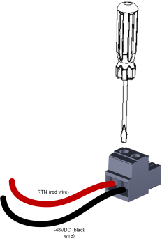
| 3. | Identify the polarity (negative and positive) of the two DC power feed wires. Polarity of power feed wires are typically color-coded, where red is positive (RTN) and black is negative (-48VDC). |
| 4. | Insert the exposed wire of one of the two DC-input power source wires into the correct opening (according to polarity) on the terminal block plug (supplied), as shown in the following figure. Make sure that only wire with insulation exits the terminal block. |
| 5. | Using a Philips or flat-head screwdriver, tighten the captive screw located above the installed wire lead to secure the wire to the terminal block. |
| 6. | Repeat steps 1 through 5 for the second wire. |
Wiring DC Power Leads to Terminal Block
| 7. | Make sure that no wire strands are left outside the connector and that all strands have been clamped under the terminal block screw. |
| 8. | Gently try and pull the wires from the terminal block. Only if the wires remain secured to the terminal block may you continue to the next step; otherwise, if the wires become free, repeat Step 5 to secure the wires to the terminal block. |
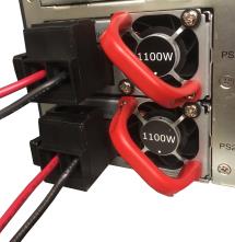
| 9. | Insert the DC terminal block plug into the DC inlet of the Power Supply module located on the device's rear panel. The following figure shows the completed wiring of the terminal block. |
Wired DC Power Supply Modules
| 10. | Connect the DC power leads to a 48-VDC power source. |